4.2. Energy and Mass Transfer#
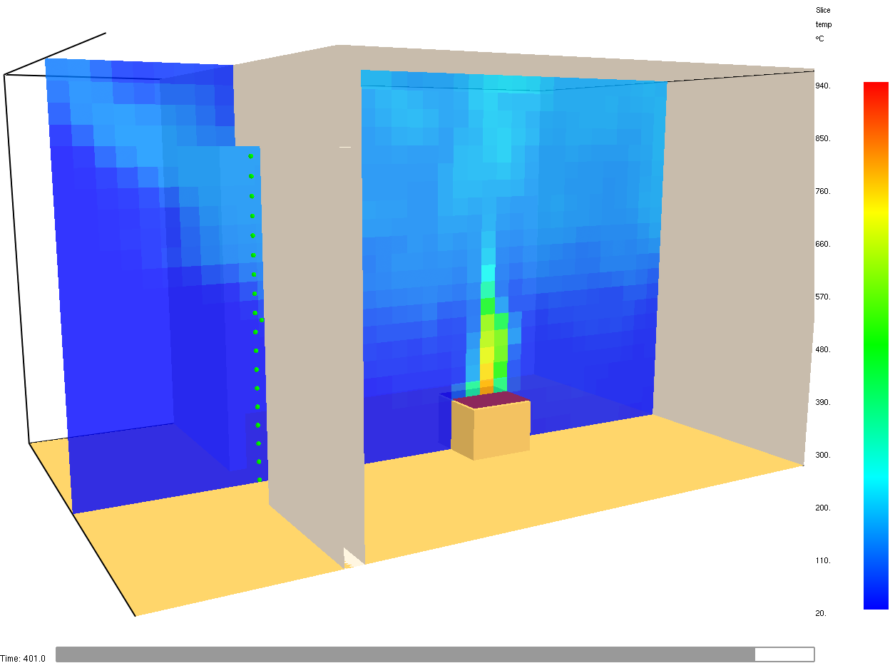
This example builds on the “Steckler compartment” [SQR82] and the energy_budget discussion in the (FDS Verification Guide, 7.2.1 The Heat from a Fire). It provides a brief overview over energy and mass transfer in terms of a simulation of a room fire experiment. As an example, the room setup with a door was chosen. The door is located at the centre of the front wall. It is 1.80 m high and 0.60 m wide.
You are provided with a pre-built FDS input file (EnergyMassTransfer.fds), which needs to be completed and adjusted through the course of this exercise. The geometry of the compartment is based on the Steckler compartment. The fluid cells are cube-shaped with an edge length of 10 cm. Thus, the ceiling height is slightly larger to align with the mesh resolution, i.e. 2.20 m instead of 2.18 m. The top surface of the burner is raised to a height of 0.30 m. It has a squared cross section with an edge length of 0.40 m. In this exercise the burner shall be supplied with propane as fuel (heat of combustion: 46420.0 kJ/kg, soot yield: 20 g/g, CO yield: 10 g/g).
Tasks#
The tasks are designed with FDS 6.7.5 in mind. For more information of specific functions please consult the respective Users Guide [MHF+20d].
Step 0 - Set Up the Simulation#
Set up the FDS input such that the gas burner provides an energy release rate of about 63 kW.
Implement slice files for density, temperature and pressure. All should show the cell-centered values.
What options do you have to implement the fuel in FDS?
Compare your desired input with the FDS response, by means of a plot.
Fig. 4.3 Check the energy release rate of the gas burner.#

Fig. 4.4 Example for slice location.#
Step 1 - Energy Transfer#
Determine the radiative fraction of the flame (Users Guide, Chapter 16 Radiation).
Determine energy conservation (Users Guide, Chapter 21.10.1 Heat Release Rate).
Fig. 4.5 Check the energy conservation.#
Step 2 - Mass Transfer#
Calculate the mass flux of fuel needed to achieve the desired energy release rate.
Record the gas temperatures in a vertical line across the centre of the doorway, within the cell centres. Also, record the gas velocities at the same locations. The results should be data-time series. Furthermore, set up devices across the door area to record the mass flow in and out of the compartment. (Chapter 21.2 Device Output: The DEVC Namelist Group, Chapter 21.10.20 Gas Velocity, Chapter 21.10.13 Spatially-Integrated Outputs)
Plot the response of some of the gas temperature devices to determine when a quasi-steady state is reached.
Create a plot that shows averaged gas temperature over the height. The data should be averaged over an interval of about 100 s. Create a similar plot for the velocities.
Based on the above plots, estimate the mass flow out of the comparment.
Compare your findings with the FDS response. Also have a look at the fuel mass flux.
On a somewhat meta-level: What do you expect, or maybe even know, is the necessary heating power for modern homes in Germany, broadly speaking?
Fig. 4.6 Temperatures in the doorway for a selected number of sensors to determine when a quasi-steady state is reached.#
Fig. 4.7 Temperatures in the centre of the doorway over the hight, averaged from 400 s to 500 s.#
Fig. 4.8 Velocities in the centre of the doorway over the hight, averaged from 400 s to 500 s.#
Fig. 4.9 Mass flow through the doorway in and out of the compartment.#
Step 3 - Pressure Build Up#
Close the door in the simulation and record the pressure change in the compartment (DEVC). Assuming the door would open towards the inside of the compartment. How large would be the force a fire fighter needs to exert to open it after 25 s of simulation time?

